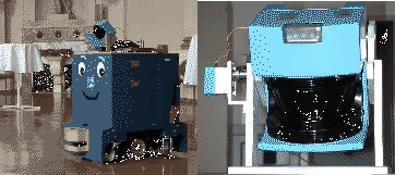
The ARIADNE robot (fig. 1) is an industrial robot
and about 80 cm ![]() 60 cm large and 90 cm high. The mobile
platform can carry a payload of 200 kg at speeds of up to
0.8 m/s. The core of the robot is a Pentium-III-800 MHz with
384 MB RAM for controlling the AIS 3D laser range finder. An
embedded PC-104 system is used to control the motor. The 3D laser
scanner [7] is built on the basis of a 2D laser range
finder by extension with a mount and a servomotor. The 2D laser
range finder is attached to the mount for being rotated. The
rotation axis is horizontal (pitch). A standard servo is
connected on the left side (fig. 1) and is
controlled by a laptop running RT-Linux [7].
60 cm large and 90 cm high. The mobile
platform can carry a payload of 200 kg at speeds of up to
0.8 m/s. The core of the robot is a Pentium-III-800 MHz with
384 MB RAM for controlling the AIS 3D laser range finder. An
embedded PC-104 system is used to control the motor. The 3D laser
scanner [7] is built on the basis of a 2D laser range
finder by extension with a mount and a servomotor. The 2D laser
range finder is attached to the mount for being rotated. The
rotation axis is horizontal (pitch). A standard servo is
connected on the left side (fig. 1) and is
controlled by a laptop running RT-Linux [7].
 |
The area of
![]() is scanned with different horizontal (181, 361, 721) and vertical
(128, 256) resolutions. A plane with 181 data points is scanned
in 13ms by the 3D laser range finder, that is a rotating mirror
device. Planes with more data points, e.g. 361, 721 duplicate or
quadruplicate this time. Thus a scan with 181
is scanned with different horizontal (181, 361, 721) and vertical
(128, 256) resolutions. A plane with 181 data points is scanned
in 13ms by the 3D laser range finder, that is a rotating mirror
device. Planes with more data points, e.g. 361, 721 duplicate or
quadruplicate this time. Thus a scan with 181 ![]() 256 data
points needs 3.4 sec. In addition to the distance measurement the
3D laser range finder is capable of quantifying the amount of
light returning to the scanner. Fig. 2 (left) shows the
hall of castle Birlinghoven wheras each voxel has an intensity
value. This scene is used throughout the paper.
256 data
points needs 3.4 sec. In addition to the distance measurement the
3D laser range finder is capable of quantifying the amount of
light returning to the scanner. Fig. 2 (left) shows the
hall of castle Birlinghoven wheras each voxel has an intensity
value. This scene is used throughout the paper.
![\begin{figure*}\begin{center}
\parbox[c]{4.2cm}{\epsfxsize=4.2cm \epsffile{grey_...
...\epsfxsize=4.2cm \epsffile{objects.eps}}\vspace*{-7mm}
\end{center}\end{figure*}](img7.png) |
The basis of the map building and planing module are algorithms for reducing points, line detection, surface extraction and object segmentation. Descriptions of these algorithms can be found in [7]. While scanning a scene, lines are detected in every scanned slice. These lines are merged into surfaces and are the basis of object segemntation, which marks occupied space. Fig. 2 shows the result of these algorithms.
Several 3D scans are necessary to digitalize environments without
occlusions. To create a correct and consistent model, the scans
have to merged in one coordinate system. This process is called
registration. Variants of the iterative closest points algorithm
[8] are used to calculate a rotation ![]() and
translation
and
translation ![]() , which aligns the 3D scans. This transformation
also corrects the estimated robot pose [9]. The 3D
digitalization and map building is a stop, scan, plan and go
setting. The next section describes the next best view planning
module.
, which aligns the 3D scans. This transformation
also corrects the estimated robot pose [9]. The 3D
digitalization and map building is a stop, scan, plan and go
setting. The next section describes the next best view planning
module.