


Next: Future work
Up: Results and Conclusion
Previous: Results and Conclusion
The proposed methods have been tested in several experiments with
our autonomous mobile robot in the GMD Robobench. Figure
4 shows an example 3D point cloud (single 3D scan
with 184576 points) and the semantic interpretation. The
corresponding original and refined model is given in figure
5 (top: Original model,  = 14.57 +
 173.09, bottom: Refined model, = 26.68 +
2.35,
173.09, bottom: Refined model, = 26.68 +
2.35,
was set to 100.0). The figure shows the
reduction of the jitters at the floor and ceiling (circled). The
orientation of the model in the bottom image is transformed along
the axis of the coordinate system and the meshing algorithm
produces flat walls. The total computation time for the
optimization is about one minute (Pentium-IV-2400).
An octree-based algorithm (19) generates the mesh
(cube width: 5cm) to visualize the differences between the
images. Starting from a cuboid surrounding the whole scene the
mesh generation recursively divides the scene into 8 smaller
cubes. Empty nodes of the resulting octree are pruned.
Figure 6:
Example of a compact flat surface model reconstructed by
an autonomous mobile robot (eight merged 3D scans). The persons
in the scene are filtered out through the plane detection.
Top left: Photo of the corridor scene.
Top middle and right: Extracted surfaces with their semantic
interpretation. Bottom left: Rendered scene with reflectance values.
Bottom middle: Unconstrained mesh. Bottom right:
Constrained mesh.
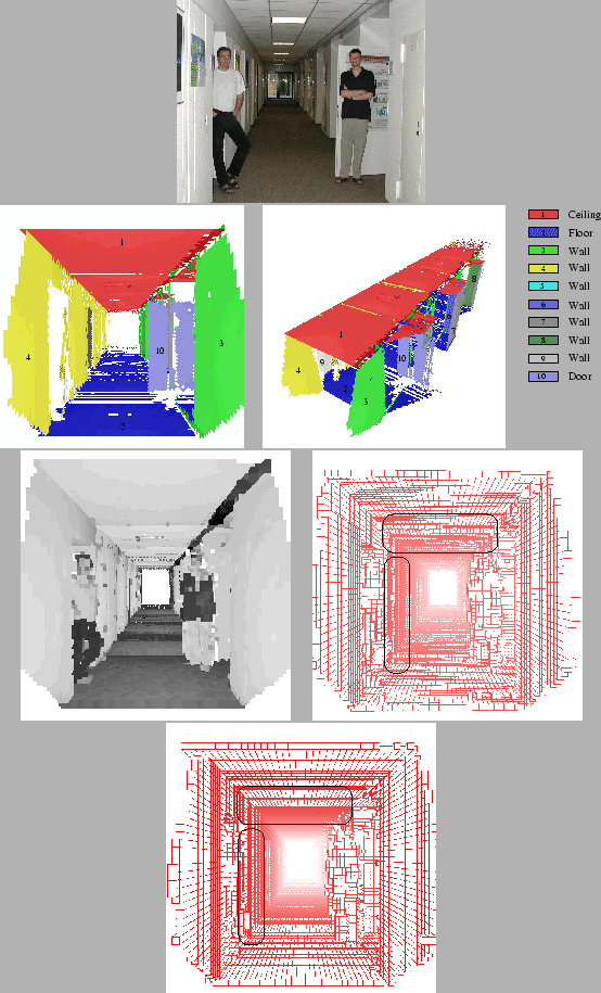 |
The second example in figure example 6 consists of
eight merged scans acquired by the autonomous mobile robot
driving in the GMD Robobench. The scene consists of a 32 meter
corridor connecting 15 offices. Two persons are standing inside
at the beginning. Figure 6 top, left shows the 3D
data and reflectance values. The next two pictures (top middle
and right) show the extracted and labeled planes. The two persons
and other non-flat objects, e.g., dynamic objects, are not
explained by the semantic net and therefore filtered from the
plane model. The door behind the right person becomes
visible. Figure 6 bottom shows the original (left)
and refined (right) octree model with marked differences. The
images contains the silhouette of two persons, because all points
not assigned to planes are unchanged and included.
Next: Future work
Up: Results and Conclusion
Previous: Results and Conclusion
root
2003-08-06