The semantic description, i.e., the ceiling and walls enable to transform the orientation of the model along the coordinate axis. Therefore it is not necessary to transform the model interactively into a global coordinate system or to stay in the coordinates given by the first 3D scan.
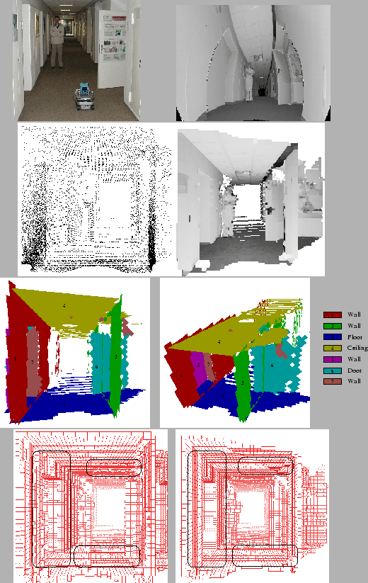 |
The proposed methods have been tested in several experiments with our autonomous mobile robot in the GMD Robobench, a standard office environment for the evaluation of autonomous mobile robots. Figure 4 shows an example 3D point cloud (single 3D scan with 58680 points) and the semantic interpretation. The figure shows the reduction of the jitters at the floor, ceiling and walls (circled). The orientation of the model in the bottom image is transformed along the axis of the coordinate system and the meshing algorithm produces flat walls. Hereby an octree-based algorithm [16] generates the mesh (cube width: 5cm). The total computation time for the complete optimization is about 2.4 seconds (Pentium-IV-2400).